


1.Scope:
1.1 General
This Standard covers overall dimensions, tolerances, ratings, testing, and markings for factory-made wrought butt welding fittings in sizes NPS 1/2 through NPS 48 (DN 15 through DN 1200).
1.2 Special Fittings
Fittings may be made to special dimensions, sizes, shapes, and tolerances by agreement between the manufacturer and the purchaser.
Fabricated laterals and other fittings employing circumferential or intersection welds are considered pipe fabrication and are not within the scope of this Standard. Fabricated lap joint stub ends are exempt from the above restrictions, provided they meet all the requirements of the applicable ASTM material specification listed in section 5.
1.4 Relevant Units
This Standard states values in both SI (Metric) and U.S. Customary units. These systems of units are to be regarded separately as standard. Within the text, the U.S. Customary units are shown in parentheses or in separate tables that appear in Mandatory Appendix I. The values stated in each system are not exact equivalents; therefore, it is required that each system of units be used independently of the other. Combining values from the two systems constitutes nonconformance with the Standard. The designation for size is NPS for both metric- and customary-dimensioned fittings. Fitting pressure rating is associated with the connecting wall thickness of pipe of equivalent size and material.
1.5 References
1.5.1 Referenced Standards.
Standards and specifications adopted by reference in this Standard are shown in Mandatory Appendix II. It is not considered practical to identify the specific edition of each standard and specification in the individual references. Instead, the specific edition reference is identified in Mandatory Appendix II. A product made in conformance with a prior edition of referenced standards and in all other respects conforming to this Standard will be considered to be in conformance.
1.5.2 Codes and Regulations.
A fitting used under the jurisdiction of the ASME Boiler and Pressure Vessel Code, the ASME Code for Pressure Piping, or a governmental regulation is subject to any limitation of that code or regulation. This includes any maximum temperature limitation or rule governing the use of a material at low temperature.
1.6 Service Conditions
Criteria for selection of fitting types and materials suitable for particular fluid service are not within the scope of this Standard.
1.7 Welding
Installation welding requirements are outside the scope of this Standard.
1.8 Quality Systems
Nonmandatory requirements relating to the fitting manufacturer’s Quality System Program are described in Nonmandatory Appendix A.
1.9 Convention
For determining conformance with this Standard, the convention for fixing significant digits where limits (maximum and minimum values) are specified, shall be as defined in ASTM E29. This requires that an observed or calculated value be rounded off to the nearest unit in the last right-hand digit used for expressing the limit. Decimal values and tolerances do not imply a particular method of measurement.
1.10 Pressure Rating
Designation Class followed by a dimensionless number is the designation for pressure–temperature ratings. Standardized designations for flanges per ASME B16.5 referenced in this Standard are Classes 150, 300, 600, 900, 1500, and 2500.
4 MARKING
4.1 Standard Marking
Each fitting shall be permanently marked to show the following:
(a)manufacturer’s name or trademark
(b) material identification, either the ASTM or ASME grade designation 2
(c) schedule number1 or nominal wall thickness in mm
(d) size — the nominal pipe size (NPS) identification number related to the end connections shall be used
(e) compliance — see para. 4.4 for standard and special fitting marking A manufacturer may supplement these mandatory markings with others, including a DN size designation, but confusion with the required marking shall be avoided.
4.2 Exceptions
Where the size of the fitting does not permit complete marking, the identification marks may be omitted in reverse of the order presented in para.
4.3 Depth of Stamping
Where steel stamps are used, care shall be taken so that the marking is not deep enough or sharp enough to cause cracks or to reduce the wall thickness of the fitting below the minimum allowed. 4.4 Compliance
4.4.1 Standard Fittings
That the fitting was manufactured in conformance with this Standard, including all dimensional requirements, is certified by a prefix “WP” in the material grade designation marking.
4.4.2 Special Fittings
That the fitting was manufactured in conformance with this Standard, except that dimensional requirements are as agreed between the purchaser and the manufacturer, is certified by a supplementary suffix to the material grade designation marking as follows:
(a)“S58” of ASTM A960 applies for fittings in accordance with ASTM A234, A403, and A420.
(b) “S8” applies for fittings in accordance with ASTM A815.
(c) “SPLD” applies for fittings in accordance with ASTM B361, B363, and B366.
5 MATERIAL Wrought fittings covered by this Standard shall be in accordance with ASTM A234, A403, A420, A815, B361, B363, B366, or the corresponding standard listed in Section II of the ASME Boiler and Pressure Vessel Code.
The term wrought denotes fittings made of pipe, tubing, plate, or forgings. Fittings made from block forgings may only be supplied subject to agreement between the manufacturer and purchaser. Such fittings need not meet the requirements of section 7.
6 FITTING DIMENSIONS
6.1 General
This Standard provides for a fixed position for the welding ends with reference to either the centerline of the fittings or the overall dimensions. Dimensional requirements for these fittings are to be found in Tables 1 through 11 and Tables I-1 through I-11 of Mandatory Appendix.
6.2 Special Dimensions
6.2.1 Fatigue Loading.
For applications where fatigue loading is a concern, required minimum dimensions shall be furnished by the purchaser.
6.2.2 Bore Diameter.
Bore diameters away from the ends are not specified. If special flow path requirements are needed, the bore dimensions shall be specified by the purchaser.
6.2.3 Stub Ends.
Service conditions and joint construction often dictate stub end length requirements. Therefore, the purchaser
must specify long or short pattern fitting when ordering. [See General Note (c) in Tables 9 and I-9.]
6.2.4 Segmental Elbows.
Factory-made segments of short radius, long radius, and 3D radius elbows may be made to meet customer angle requirements. With the exception of the B dimension, factory-made segments of elbows shall meet all other requirements of this Standard. The B dimension for segmented elbows can be calculated as follows:
For segments of 90-deg elbows Bs=A×tan(θ/2) where A p dimension A for appropriate 90-deg elbow being segmented from (a) Table 1/Table I-1 for long radius elbow, mm (in.) (b) Table 4/Table I-4 for short radius elbow, mm (in.) (c) Table 6/Table I-6 for 3D elbow, mm (in.) Bs p center-to-end dimension for segmented elbow θ angle of segmented elbow — 30 deg, 60 deg, 75 deg, etc.
When special elbows are intended for field segmenting, the outside or inside diameter tolerance shall be furnished throughout the fitting by agreement between the manufacturer and the purchaser. Any mismatch on the outside or inside diameter needs to be corrected in the field by grinding, back-welding, or bridging of weld to meet the applicable piping code requirements. Although the elbow intended for fieldsegmenting must meet the requirements of this Standard, once the field-segmented elbow is cut, it is not a B16.9 product.
7 SURFACE CONTOURS
Where adjacent openings in fittings are not in parallel planes, they shall be joined by a circular arc or radius on the external surfaces. The arc or radius may be terminated in tangents. Except as provided for block forgings (see section 5), the projected profile of external surfaces of fittings shall not have sharp intersections (corners) and/or collapsed arcs.
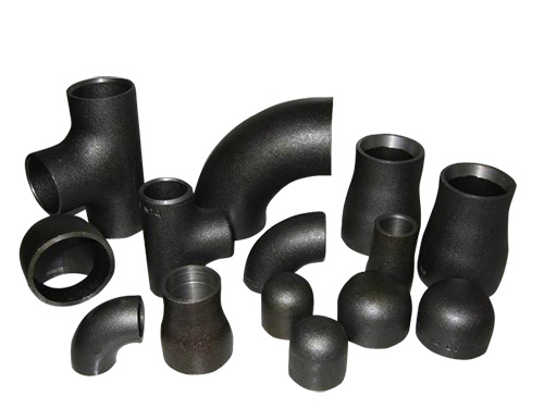
ASME B16.9 Carbon Steel Butt Weld Pipe Fittings
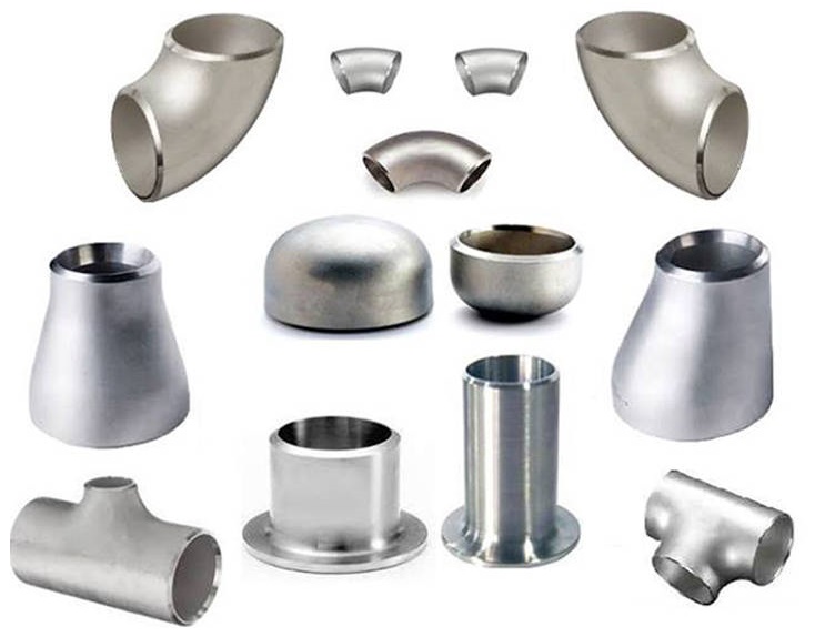
ASME B16.9 Stainless Steel Butt Weld Pipe Fittings
Product List: Butt Weld 45 Deg Lr Elbow | Butt Weld 90 Deg Lr Elbow | Butt Weld 180 Deg Lr Elbow | Butt Weld Reducing 90 Deg Lr Elbow | Butt Weld 90 Deg Sr Elbow | Butt Weld 180 Deg Sr Elbow | Butt Weld 45 Deg 3D Elbow | Butt Weld 90 Deg 3D Elbow | Butt Weld Equal Tee | Butt Weld Reducing Tee | Butt Weld Equal Cross | Butt Weld Reducing Cross | Butt Weld Cap | Butt Weld Concentric Reducer | Butt Weld Eccentric Reducer | Stub Ends


