


1.SCOPE
1.1 This specification covers factory-made, seamless and electric fusion-welded carbon and low-alloy steel, butt-welding fittings for use in high pressure gas and oil transmission and distribution systems, including pipelines, compressor statjons~ metering and regulating stations, and mains.
1.2 This Standard Practice governs dimensions, tolerances, ratings, testing, materials, chemical and tensile properties, heat treatment, notch toughness properties, manufacture and marking for high-test, butt-welding fittings NPS 60 and smaller. Dimensional requirements for NPS 14 and smaller are provided by reference to ASME B 16.9.
1.3 The term “welding fittings” applies to buttwelding fittings such as elbows, segments of elbows, return bends, caps, tees, single-or multiple-outlet extruded headers, reducers, and factory-welded extensions and transition sections.
1.4 Fittings may be made to special dimensions, sizes, shapes, and tolerances, or of wrought materials other than those covered by this Standard Practice by agreement between the manufacturer and the purchaser. When such fittings meet all other stipulations of this Standard Practice they shall be considered as being in partial compliance therewith, providing they are appropriately marked.
1.4.1 Fittings manufactured in partial compliance, as provided in Section 1.4, shall be identified with “Part” following the respective grade designation.
2.PRESSURE RATING
2.1 The allowable internal-pressure ratings for pipe fittings designed in accordance with this Standard Practice shall be calculated as for straight seamless pipe (or welded pipe with a joint efficiency factor of 1.0) of equivalent grade, diameter and wall thickness in accordance with the rules established in the applicable sections of ASME B31.
2.2 All fittings produced in accordance with this Standard Practice shall be designed to withstand a field hydrostatic test pressure, after installation, at a pressure level equivalent to that required to develop a hoop stress equal to the specified-minimum yield strength for pipe ofequivalcnt grade and wall thickness based on Barlow’s Formula, without failure, leakage, or impairment of serviceability. Barlow’s formula is defined as:
2.3 By agreement between the manufacturer and the purchaser, fittings may be tested at a higher pressure providing the manufacturer is notified of the test pressure to be used.
2.4 The design shall take into consideration performance requirements prescribed above as well as additional factors dictated by the shape of the part.
2.5 The design of fittings may be established by mathematical analyses contained in nationally recognized pressure vessel or piping codes or, at the manufacturer’s option, by proof testing in accordance with Section 4. The design of fittings that cannot be qualified by mathematical analyses shall be established by proof testing in accordance with Section 4.
3.SIZE
3.1 The nominal size of the fittings refers to the nominal O.D. of the pipe to which it is attached.
4.DESIGN PROOF-TEST
4.1 Proof tests shall be made as set forth herein as evidence of the adequacy of the design references in Section 2. Records of design or successful proof tests shall be available at the manufachlrer’s facility for inspection by the purchaser.
4.2 Unless otherwise agreed upon between manufacturer and purchaser, the only required proof test is a bursting strength test.
4.2.1 Prototype fittings that are representative of production and selected for test shall be identified as to material, grade, and lot, including heat treatment. They shall be inspected for dimensional compliance to this Standard Practice.
4.2.2 Straight seamless or welded pipe sections, with a calculated burst strength at least as great as that calculated for the fittings, shall be welded to each end of the fitting to be tested. Any internal misalignment greater than 0.06 inch shall be reduced by taper boring at a slope not over a 1 to 3 ratio. The length of pipe sections for closures shall be at least twice the pipe O.D.
4.2.2.1 Shorter lengths may be used as follows:
1) The assembly must withstand at least 105 per cent of the proof-test pressure computed in Section
2)Minimum length of pipe shall be one pipe O.D. for NPS 14 and smaller.
3) Minimum length of pipe shall be one-halfpipe O.D. for sizes larger than NPS 14.
4.2.2.2 Test fluid shall be water or other liquid used for hydrostatic testing.
4.2.3 Hydrostatic pressure shall be applied until the fitting ruptures. The actual test pressure prior to rupture must at least equal the computed proof-test pressure. Alternately, the test is successful if the assembly withstands, without rupture, 105 percent of the computed proof-test pressure defined in Section
4.3 A successful proof test on a prototype fitting selected as required in Section 4.2.1 may be used to qualify other fittings to the extent described herein.
4.3.1 One test fitting may be used to qualify fittings of similar designs that are no smaller than onehalf nor larger than two times the size of the test fitting.
4.3.2 The test of a non-reducing fitting qualifies reducing fittings that are of the same pattern.
4.3.3 The untested fitting must have a t / D ratio not less than one-half nor more than three times the t / D of the test fitting.
4.3.4 The pressure retaining capacity of a fitting made of various grades of steel will be essentially directly proportional to the tensile properties of the various grades .. Hence, it is necessary to test a prototype in only a single grade to prove the geometric design of the fitting.
4.3.5 A test on a prototype elbow qualifies elbows having longer radii than the test fitting providing they qualify under Sections 4.3.1 and 4.3.3.
5.HYDROSTATIC TESTING
5.1 Welding fittings shall be capable of withstanding a hydrostatic test-pressure as specified in Section 2.2, but hydrostatic testing by the manufachlrer is not required.
6.MATERIALS
6.1 The steel shall be fully killed and made using recognized melting practices to provide intended heat-treat response and notch-toughness properties. Steel shall be made by open hearth, basic oxygen, or electric furnace process and shall be suitable for field welding to other fittings, flanges, and pipe manufactured under the following specifications: ASTMA53, A 106, A381, A234, A420, A105, A694, or the corresponding ASME standard, or API 5L, and :MSS SP-44.
6.2 The material for fittings shall consist of blooms, billets, slabs, forging quality bar, plate, seamless or fusion-welded tubular products with filler metal added.
6.3 The steel used shall be suitable welding-quality carbon steels or of a suitable welding-quality high-strength, low-alloy steel.
6.4 If preheating of the material is required to insure proper weldability under normal field conditions, the manufacturer shall state specific preheat requirements and permanently indicate this on the fitting.
| Grades | ASTM A860 WPHY 42 Pipe Fittings, ASTM A860 WPHY 46 Pipe Fittings, ASTM A860 WPHY 52 Pipe Fittings, ASTM A860 WPHY 60 Pipe Fittings, ASTM A860 WPHY 65 Pipe Fittings, ASTM A860 WPHY 70 Pipe Fittings |
| Type | Elbows, Long Radius Elbow, Short Radius Elbow, Bend, Long Radius Bends, Piggable Bends, Tee, Equal Tee, Reducing Tee, Cross, Reducer, Concentric Reducer, Eccentric Reducer, Pipe End Caps. |
| Dimensions | ANSI/ASME B16.9, B16.28, MSS-SP-43. |
| Thickness | Sch 10, 20, 40, STD, 60, 80, XS, 100, 120, 140, 160 Sch XXS. |
| Specification- Grade | ASTM A860 – MSS-SP-75 WPHY 42 / 46 / 52 / 56 / 60 / 65 / 70. |
| Type | Seamless / Welded / Fabricated |
| Size | Seamless ½” to 24”, Welded ½” to 24”, Two Joint / Two Halve Fittings 6” to 48” |
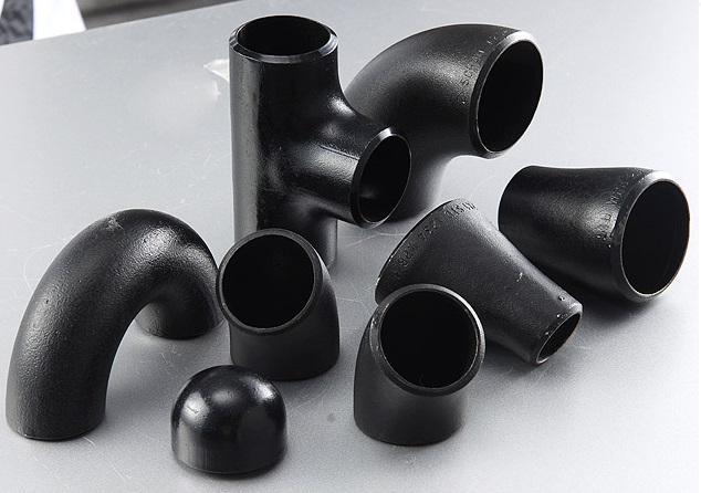
MSS SP75 Carbon Steel Butt Welding Fittings
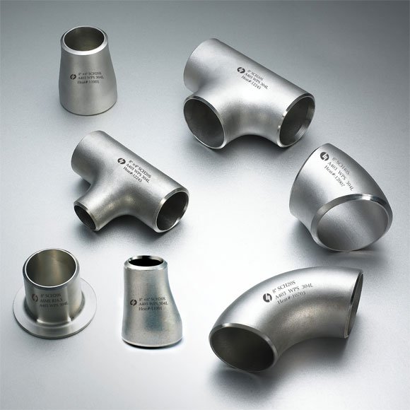
MSS SP75 Stainless Steel Butt Welding Fittings
MSS SP75 – Wrought High-Strength Low-Alloy Steel Butt-Welding Fittings Contains: Butt Weld 45 Deg Lr Elbow | Butt Weld 90 Deg Lr Elbow | Butt Weld 3D Elbow | Butt Weld Equal Tee | Butt Weld Reducing Tee | Butt Weld Cap | Butt Weld Concentric Reducer | Butt Weld Eccentric Reducer.


